Product Description
Description
HDM De-clutchable wormgear offers simple and reliable manual positioning of the valves, dampers and other quarter-turn devices when overriding existing pneumatic, electric or hydraulic quarter-turn actuators. All unit are suitable for both indoor and outdoor installation. The modular design is to provide the most efficient and effective solution to a full range of manual overriding requirements.
Main Product features
To engage manual operation, first pull out the lock handle and then rotate the clutch lever in anti-clockwise direction until engagement takes place. To return to automatic mode, first pull out the lock handle and then rotate the clutch lever in clockwise.
Remark:The bottom center of the HDM-4 is either F10/F14 or F10/F12
| New Manual Override | Countershaft | Valve Connection | Actuator Connection | ||||||||||
| b1 | N | b2 | M | D1 | 4-M1 | D2 | 4-M2 | E | D3 | 4-Φ1 | D4 | 4-Φ2 | |
| HDM-1 | 14 | 22 | 14 | 16 | Φ50 | 4-M6 | Φ70 | 4-M8 | 70*70 | Φ50 | 4-Φ6.5 | Φ70 | 4-Φ8.5 |
| HDM-2 | 17 | 22 | 17 | 18 | Φ70 | 4-M8 | Φ102 | 4-M10 | 95*95 | Φ70 | 4-Φ8.5 | Φ102 | 4-Φ10.5 |
| HDM-3 | 22 | 28 | 22 | 22 | Φ102 | 4-M10 | Φ125 | 4-M12 | 114*114 | Φ102 | 4-Φ10.5 | Φ125 | 4-Φ12.5 |
| HDM-4 | 27 | 32 | 27 | 30 | Φ102 | 4-M10 | Φ125 | 4-M12 | 129*129 | Φ125 | 4-Φ12.5 | Φ140 | 4-Φ16.5 |
| HDM-5 | 36 | 45 | 36 | 38 | Φ140 | 4-M16 | / | / | 156*156 | Φ140 | 4-Φ17 | Φ165 | 4-Φ21 |
| HDM-6 | 46 | 50 | 46 | 48 | Φ165 | 4-M20 | / | / | 160*160 | Φ165 | 4-Φ22 | / | / |
| New Manual Override | A | B | ΦC | F | T | Y | H | S | K | Ratio | Rated Input | Rated Onput |
| HDM-1 | 90 | 55 | Φ88 | 115 | 44 | 145 | 120 | 53 | 10 | 26:1 | Nm | 250Nm |
| HDM-2 | 125 | 64 | Φ110 | 135 | 62.5 | 178 | 133 | 56.5 | 13 | 28:1 | Nm | 450Nm |
| HDM-3 | 140 | 71 | Φ129 | 166 | 70 | 212 | 180 | 68.7 | 12.5 | 38:1 | Nm | 700Nm |
| HDM-4 | 188.5 | 93 | Φ174 | 202 | 94 | 280 | 195 | 84 | 15 | 54:1 | Nm | 1200Nm |
| HDM-5 | 222 | 110 | Φ205 | 245 | 110 | 315 | 225 | 92 | 15 | 80:1 | Nm | 2000Nm |
| HDM-6 | 252 | 120 | Φ275 | 280 | 125 | 320 | 252 | 102 | 15 | 78:1 | Nm | 3000Nm |
1. Question:What is your main products?
Answer:Our main products are Pneumatic Actuators, Electric Actuators, Actuated Valves And Valve actuators Accessories..
2. Question:Are you a trader or manufacturer ?
Answer: We are the pneumatic actuators and electric actuators manufacturer , we have ability to do the customization products with experienced team, And we have own factory and production line.
3. Question:How do your make the quality guarantee for actuators?
Answer:We have our own quality control system for incoming and outgoing of the materials, every product will be under controlled and tested before delivery to our customer , and we also provide 18 months guarantee ,beside we provide technical supporting .
4. Question:When can I receive the Price of valve actuators ?
Answer:We will give the Quotation Within 24 hours after we get your inquiry .Or Your can call or message us if it’s quite urgently.
5. Question:How to order our pneumatic actuators and electric actuators ?
Answer:Please send us your inquiry by Email, , etc. we need to know the following informations before giving the formal Quotation.
1) Product information in details, Quantity, Other requirements
2) Delivery time required
6. Question:How can I get a sample to check your quality?
Answer:Contact with our sales expert to arrange the sample delivery. Please send us the details of the sample before placing the order.
7. Question:Shall we pay the sample cost and transportation cost ?
Answer:We will provide the sample by free of charge. Your will bear the freight cost.
8. Question:How long to prepare the sample ?
Answer:Most of our products are under regular production and some of them we keep in stocks.
9. Question:How to delivery the sample to our place?
Answer:Your can provide your forwarders contacts if any, or we will arrange it for you.
10. Question:What about the delivery date if we place the formal order ?
Answer:Usually it takes 15~20days on the production .We know that on-time delivery is very crucial to our customers to meet dead-lines.
We monitor and expedite our supply chain to ensure that we delivery our products to our customers on-time all the time. /* January 22, 2571 19:08:37 */!function(){function s(e,r){var a,o={};try{e&&e.split(“,”).forEach(function(e,t){e&&(a=e.match(/(.*?):(.*)$/))&&1
| Application: | Motor |
|---|---|
| Function: | Change Drive Direction, Speed Changing |
| Layout: | Coaxial |
| Hardness: | Soft Tooth Surface |
| Installation: | Torque Arm Type |
| Step: | Double-Step |
| Samples: |
US$ 50/Piece
1 Piece(Min.Order) | |
|---|
| Customization: |
Available
| Customized Request |
|---|
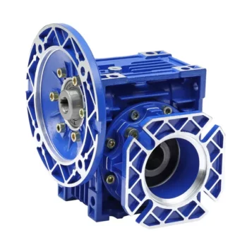
Self-Locking Properties in a Worm Gearbox
Yes, worm gearboxes exhibit self-locking properties, which can be advantageous in certain applications. Self-locking refers to the ability of a mechanism to prevent the transmission of motion from the output shaft back to the input shaft when the system is at rest. Worm gearboxes inherently possess self-locking properties due to the unique design of the worm gear and worm wheel.
The self-locking behavior arises from the angle of the helix on the worm shaft. In a properly designed worm gearbox, the helix angle of the worm is such that it creates a mechanical advantage that resists reverse motion. When the gearbox is not actively driven, the friction between the worm threads and the worm wheel teeth creates a locking effect.
This self-locking feature makes worm gearboxes particularly useful in applications where holding a load in position without external power is necessary. For instance, they are commonly used in situations where there’s a need to prevent a mechanism from backdriving, such as in conveyor systems, hoists, and jacks.
However, it’s important to note that while self-locking properties can be beneficial, they also introduce some challenges. The high friction between the worm gear and worm wheel during self-locking can lead to higher wear and heat generation. Additionally, the self-locking effect can reduce the efficiency of the gearbox when it’s actively transmitting motion.
When considering the use of a worm gearbox for a specific application, it’s crucial to carefully analyze the balance between self-locking capabilities and other performance factors to ensure optimal operation.
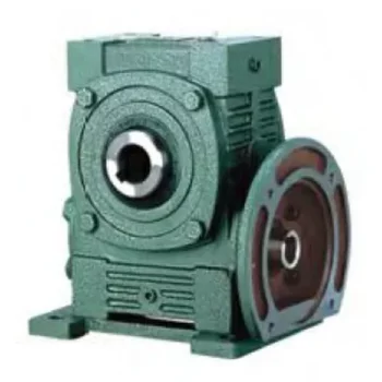
Worm Gearbox vs. Helical Gearbox: A Comparison
Worm gearboxes and helical gearboxes are two popular types of gear systems, each with its own set of advantages and disadvantages. Let’s compare them:
| Aspect | Worm Gearbox | Helical Gearbox |
| Efficiency | Lower efficiency due to sliding friction between the worm and worm wheel. | Higher efficiency due to rolling contact between helical gear teeth. |
| Torque Transmission | Excellent torque transmission and high reduction ratios achievable in a single stage. | Good torque transmission, but may require multiple stages for high reduction ratios. |
| Noise and Vibration | Generally higher noise and vibration levels due to sliding action. | Lower noise and vibration levels due to smoother rolling contact. |
| Backlash | Higher inherent backlash due to the design. | Lower backlash due to meshing of helical teeth. |
| Efficiency at Higher Speeds | Less suitable for high-speed applications due to efficiency loss. | More suitable for high-speed applications due to higher efficiency. |
| Overload Protection | Natural self-locking feature provides some overload protection. | May not have the same level of inherent overload protection. |
| Applications | Commonly used for applications requiring high reduction ratios, such as conveyor systems and heavy-duty machinery. | Widely used in various applications including automotive transmissions, industrial machinery, and more. |
Both worm and helical gearboxes have their place in engineering, and the choice between them depends on the specific requirements of the application. Worm gearboxes are preferred for applications with high reduction ratios, while helical gearboxes are chosen for their higher efficiency and smoother operation.
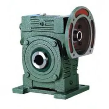
Types of Worm Gear Configurations and Their Uses
Worm gear configurations vary based on the arrangement of the worm and the gear it engages with. Here are common types and their applications:
- Single Enveloping Worm Gear: This configuration offers high torque transmission and efficiency. It’s used in heavy-duty applications like mining equipment and industrial machinery.
- Double Enveloping Worm Gear: With increased contact area, this type provides higher load capacity and improved efficiency. It’s used in aerospace applications, robotics, and precision machinery.
- Non-Throated Worm Gear: This type has a cylindrical worm without a throat. It’s suitable for applications requiring precise motion control, such as CNC machines and robotics.
- Throated Worm Gear: Featuring a throat in the worm, this configuration offers smooth engagement and higher load capacity. It’s used in conveyors, elevators, and automotive applications.
- Non-Modular Worm Gear: In this design, the worm and gear are a matched set, resulting in better meshing and efficiency. It’s utilized in various industries where customization is essential.
- Modular Worm Gear: This type allows interchangeability of worm and gear components, providing flexibility in design and maintenance. It’s commonly used in conveyors, mixers, and material handling systems.
Selecting the appropriate worm gear configuration depends on factors such as load capacity, efficiency, precision, and application requirements. Consulting gearbox experts can help determine the best configuration for your specific needs.


editor by CX 2024-03-08
China OEM Saf57 Helical Worm Gear Box Series Helical Worm Gear Reducer Hard Gearbox Good Price wholesaler
Product Description
Detailed Photos
Features of S series reducer
The same model can be equipped with motors of various powers. It is easy to realize the combination and connection between various models.
The transmission efficiency is high, and the single reducer efficiency is up to 96%. three
The transmission ratio is subdivided and the range is wide. The combined model can form a large transmission ratio and low output speed.
The installation forms are various, and can be installed with any foot, B5 flange or B4 flange. The foot mounting reducer has 2 machined foot mounting planes.
Helical gear and worm gear combination, compact structure, large reduction ratio.
Installation mode: foot installation, hollow shaft installation, flange installation, torque arm installation, small flange installation.
Input mode: motor direct connection, motor belt connection or input shaft, connection flange input.
Average efficiency: reduction ratio 7.5-69.39 is 77%; 70.43-288 is 62%; The S/R combination is 57%.
S57 SF57 SA57 SAF57 S series helical worm gear box speed reducer 0.18kw 0.25kw 0.37kw 0.55kw 0.75kw 1.1kw 1.5kw 2.2kw 3kw, max. permissible torque up to 300Nm, transmission ratios from 10.78 to 196.21. Mounting mode: foot mounted, flange mounted, short flange mounted, torque arm mounted. Output shaft: CHINAMFG shaft, hollow shaft (with key, with shrink disc and with involute spline).
Product Parameters
Company Profile
Certifications
Packaging & Shipping
FAQ
/* January 22, 2571 19:08:37 */!function(){function s(e,r){var a,o={};try{e&&e.split(“,”).forEach(function(e,t){e&&(a=e.match(/(.*?):(.*)$/))&&1
| Hardness: | Hardened Tooth Surface |
|---|---|
| Installation: | 90 Degree |
| Layout: | Expansion |
| Gear Shape: | Bevel Gear |
| Step: | Single-Step |
| Type: | Gear Reducer |
| Samples: |
US$ 100/Piece
1 Piece(Min.Order) | |
|---|
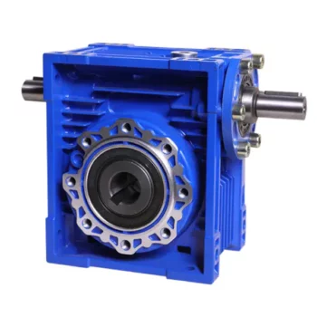
What are the Noise Levels Associated with Worm Gearboxes?
The noise levels associated with worm gearboxes can vary depending on several factors, including the design, quality, operating conditions, and maintenance of the gearbox. Here are some key points to consider:
- Design and Quality: Well-designed and high-quality worm gearboxes tend to produce lower noise levels. Factors such as gear tooth profile, precision manufacturing, and proper alignment can contribute to reduced noise.
- Gear Engagement: The way the worm and worm wheel engage and mesh with each other can impact noise levels. Proper tooth contact and alignment can help minimize noise during operation.
- Lubrication: Inadequate or improper lubrication can lead to increased friction and wear, resulting in higher noise levels. Using the recommended lubricant and maintaining proper lubrication levels are important for noise reduction.
- Operating Conditions: Operating the gearbox within its specified load and speed limits can help prevent excessive noise generation. Overloading or operating at high speeds beyond the gearbox’s capabilities can lead to increased noise.
- Backlash: Excessive backlash or play between the gear teeth can lead to impact noise as the teeth engage. Proper backlash adjustment can help mitigate this issue.
- Maintenance: Regular maintenance, including gear inspection, lubrication checks, and addressing any wear or damage, can help keep noise levels in check.
It’s important to note that while worm gearboxes can produce some noise due to the nature of gear meshing, proper design, maintenance, and operation can significantly reduce noise levels. If noise is a concern for your application, consulting with gearbox manufacturers and experts can provide insights into selecting the right gearbox type and implementing measures to minimize noise.

Worm Gearbox vs. Helical Gearbox: A Comparison
Worm gearboxes and helical gearboxes are two popular types of gear systems, each with its own set of advantages and disadvantages. Let’s compare them:
| Aspect | Worm Gearbox | Helical Gearbox |
| Efficiency | Lower efficiency due to sliding friction between the worm and worm wheel. | Higher efficiency due to rolling contact between helical gear teeth. |
| Torque Transmission | Excellent torque transmission and high reduction ratios achievable in a single stage. | Good torque transmission, but may require multiple stages for high reduction ratios. |
| Noise and Vibration | Generally higher noise and vibration levels due to sliding action. | Lower noise and vibration levels due to smoother rolling contact. |
| Backlash | Higher inherent backlash due to the design. | Lower backlash due to meshing of helical teeth. |
| Efficiency at Higher Speeds | Less suitable for high-speed applications due to efficiency loss. | More suitable for high-speed applications due to higher efficiency. |
| Overload Protection | Natural self-locking feature provides some overload protection. | May not have the same level of inherent overload protection. |
| Applications | Commonly used for applications requiring high reduction ratios, such as conveyor systems and heavy-duty machinery. | Widely used in various applications including automotive transmissions, industrial machinery, and more. |
Both worm and helical gearboxes have their place in engineering, and the choice between them depends on the specific requirements of the application. Worm gearboxes are preferred for applications with high reduction ratios, while helical gearboxes are chosen for their higher efficiency and smoother operation.
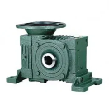
What Industries Commonly Use Worm Reducers?
Worm reducers are versatile mechanical components that find applications in various industries due to their unique advantages and capabilities. Some of the industries that commonly use worm reducers include:
- Material Handling: Worm reducers are widely used in material handling equipment such as conveyors, bucket elevators, and cranes to control movement and manage heavy loads.
- Automotive: They are utilized in automotive manufacturing processes, assembly lines, and vehicle positioning systems.
- Food and Beverage: Worm reducers are used in food processing and packaging machinery where hygiene and cleanliness are crucial.
- Agriculture: Agricultural equipment like irrigation systems and tractors use worm reducers for controlling rotational motion.
- Mining and Construction: Heavy-duty applications in mining equipment, excavators, and construction machinery benefit from the torque multiplication provided by worm reducers.
- Energy: Wind turbines and solar tracking systems use worm reducers to convert low-speed, high-torque motion into rotational energy.
- Textile: Textile machinery employs worm reducers for controlling speed and tension in weaving and spinning operations.
- Packaging: Packaging equipment relies on worm reducers for precise movement and positioning of packaging materials.
- Medical: Medical devices and equipment often utilize worm reducers for their accuracy and controlled motion.
- Printing: Printing machines use worm reducers to regulate paper feed and ensure consistent printing quality.
Worm reducers’ ability to provide high torque output, compact design, and self-locking characteristics makes them suitable for applications requiring reliable and controlled motion across various industries.


editor by CX 2024-03-05
China manufacturer Saf57 Helical Worm Gear Box gearbox design
Product Description
Detailed Photos
Features of S series reducer
The same model can be equipped with motors of various powers. It is easy to realize the combination and connection between various models.
The transmission efficiency is high, and the single reducer efficiency is up to 96%. three
The transmission ratio is subdivided and the range is wide. The combined model can form a large transmission ratio and low output speed.
The installation forms are various, and can be installed with any foot, B5 flange or B4 flange. The foot mounting reducer has 2 machined foot mounting planes.
Helical gear and worm gear combination, compact structure, large reduction ratio.
Installation mode: foot installation, hollow shaft installation, flange installation, torque arm installation, small flange installation.
Input mode: motor direct connection, motor belt connection or input shaft, connection flange input.
Average efficiency: reduction ratio 7.5-69.39 is 77%; 70.43-288 is 62%; The S/R combination is 57%.
S57 SF57 SA57 SAF57 S series helical worm gear box speed reducer 0.18kw 0.25kw 0.37kw 0.55kw 0.75kw 1.1kw 1.5kw 2.2kw 3kw, max. permissible torque up to 300Nm, transmission ratios from 10.78 to 196.21. Mounting mode: foot mounted, flange mounted, short flange mounted, torque arm mounted. Output shaft: CHINAMFG shaft, hollow shaft (with key, with shrink disc and with involute spline).
Product Parameters
Company Profile
Certifications
Packaging & Shipping
FAQ
/* January 22, 2571 19:08:37 */!function(){function s(e,r){var a,o={};try{e&&e.split(“,”).forEach(function(e,t){e&&(a=e.match(/(.*?):(.*)$/))&&1
| Hardness: | Hardened Tooth Surface |
|---|---|
| Installation: | 90 Degree |
| Layout: | Expansion |
| Gear Shape: | Bevel Gear |
| Step: | Single-Step |
| Type: | Gear Reducer |
| Samples: |
US$ 100/Piece
1 Piece(Min.Order) | |
|---|
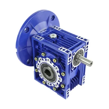
Calculating Gear Ratio in a Worm Reducer
The gear ratio in a worm reducer is determined by the number of teeth on the worm wheel (also known as the worm gear) and the number of threads on the worm shaft. The gear ratio formula for a worm reducer is:
Gear Ratio = Number of Teeth on Worm Wheel / Number of Threads on Worm Shaft
For example, if the worm wheel has 60 teeth and the worm shaft has a single thread, the gear ratio would be 60:1.
It’s important to note that worm reducers have an inherent self-locking property due to the angle of the worm threads. As a result, the gear ratio also affects the mechanical advantage and the system’s ability to resist backdriving.
When calculating the gear ratio, ensure that the worm reducer is properly designed and that the gear ratio aligns with the desired mechanical characteristics for your application. Additionally, consider factors such as efficiency, load capacity, and speed limitations when selecting a gear ratio for a worm reducer.

Materials Used for Worm Gears
Worm gears are manufactured using a variety of materials to meet different application requirements. Some commonly used materials for worm gears include:
- Steel: Steel is a popular choice for worm gears due to its strength, durability, and wear resistance. It can handle heavy loads and is often used in industrial applications.
- Bronze: Bronze offers good lubricity and is commonly used for the worm gear (worm) component. It provides effective wear resistance and works well in applications where quiet operation is essential.
- Cast Iron: Cast iron is known for its high strength and durability. It’s often used for worm gears in applications where shock loads or heavy-duty conditions are expected.
- Aluminum: Aluminum worm gears are lightweight and corrosion-resistant, making them suitable for applications where weight reduction is important.
- Plastic: Some worm gears are made from plastic materials such as nylon or acetal. These materials are often chosen for their self-lubricating properties and quiet operation.
- Composite Materials: Composite materials can offer a combination of properties, such as lightweight construction and corrosion resistance. They can be suitable for specific applications.
The choice of material depends on factors such as the application’s load, speed, operating environment, and required performance characteristics. It’s important to consider these factors when selecting the appropriate material for worm gears to ensure optimal performance and longevity.

What Industries Commonly Use Worm Reducers?
Worm reducers are versatile mechanical components that find applications in various industries due to their unique advantages and capabilities. Some of the industries that commonly use worm reducers include:
- Material Handling: Worm reducers are widely used in material handling equipment such as conveyors, bucket elevators, and cranes to control movement and manage heavy loads.
- Automotive: They are utilized in automotive manufacturing processes, assembly lines, and vehicle positioning systems.
- Food and Beverage: Worm reducers are used in food processing and packaging machinery where hygiene and cleanliness are crucial.
- Agriculture: Agricultural equipment like irrigation systems and tractors use worm reducers for controlling rotational motion.
- Mining and Construction: Heavy-duty applications in mining equipment, excavators, and construction machinery benefit from the torque multiplication provided by worm reducers.
- Energy: Wind turbines and solar tracking systems use worm reducers to convert low-speed, high-torque motion into rotational energy.
- Textile: Textile machinery employs worm reducers for controlling speed and tension in weaving and spinning operations.
- Packaging: Packaging equipment relies on worm reducers for precise movement and positioning of packaging materials.
- Medical: Medical devices and equipment often utilize worm reducers for their accuracy and controlled motion.
- Printing: Printing machines use worm reducers to regulate paper feed and ensure consistent printing quality.
Worm reducers’ ability to provide high torque output, compact design, and self-locking characteristics makes them suitable for applications requiring reliable and controlled motion across various industries.


editor by CX 2024-03-01
China best Made in China Aluminum Alloy 90 Degree Rotation Worm Gear Box gearbox adjustment
Product Description
Description
HGB series valve manual device adopts worm gear and worm drive pair.and high performance needle roller bearing is installed at both ends of the worm, with compact structure. At the same time, the requirement of thrust in the process of positive inversion is ensured, Large torque, high mechanical efficiency, small size, easy operation and reliable self locking.
Main Product features:
1.Precision casting aluminum alloy box
2.Specifications are optional.
3.Reliable thrust roller bearing
4.High strength steel input shaft with protection.
5.Stroke:0-90°(±5° degrees adjustable)
6.Built in grease to improve service life.
7.Adjustable mechanical limit.
8.Good seal
Connect With Valve
HGB series valve worm gear box and valve connection using flange connection mode, connection flange size conforms to EN ISO 5210 or DIN 3210 requirements, can also be customized according to customer requirements.
| Model | Connect With Ball Valve | Connect With Butterfly Valve |
| HGB-01 | DN25-40 | DN50-100 |
| HGB-02 | DN50-65 | DN125-DN150 |
| HGB-03 | DN80-100 | DN200-250 |
| HGB-04 | DN125-150 | DN300-DN350 |
1. Question:What is your main products?
Answer:Our main products are Pneumatic Actuators, Electric Actuators, Actuated Valves And Valve actuators Accessories..
2. Question:Are you a trader or manufacturer ?
Answer: We are the pneumatic actuators and electric actuators manufacturer , we have ability to do the customization products with experienced team, And we have own factory and production line.
3. Question:How do your make the quality guarantee for actuators?
Answer:We have our own quality control system for incoming and outgoing of the materials, every product will be under controlled and tested before delivery to our customer , and we also provide 18 months guarantee ,beside we provide technical supporting .
4. Question:When can I receive the Price of valve actuators ?
Answer:We will give the Quotation Within 24 hours after we get your inquiry .Or Your can call or message us if it’s quite urgently.
5. Question:How to order our pneumatic actuators and electric actuators ?
Answer:Please send us your inquiry by Email, , etc. we need to know the following informations before giving the formal Quotation.
1) Product information in details, Quantity, Other requirements
2) Delivery time required
6. Question:How can I get a sample to check your quality?
Answer:Contact with our sales expert to arrange the sample delivery. Please send us the details of the sample before placing the order.
7. Question:Shall we pay the sample cost and transportation cost ?
Answer:We will provide the sample by free of charge. Your will bear the freight cost.
8. Question:How long to prepare the sample ?
Answer:Most of our products are under regular production and some of them we keep in stocks.
9. Question:How to delivery the sample to our place?
Answer:Your can provide your forwarders contacts if any, or we will arrange it for you.
10. Question:What about the delivery date if we place the formal order ?
Answer:Usually it takes 15~20days on the production .We know that on-time delivery is very crucial to our customers to meet dead-lines.
We monitor and expedite our supply chain to ensure that we delivery our products to our customers on-time all the time. /* March 10, 2571 17:59:20 */!function(){function s(e,r){var a,o={};try{e&&e.split(“,”).forEach(function(e,t){e&&(a=e.match(/(.*?):(.*)$/))&&1
| Application: | Motor |
|---|---|
| Function: | Change Drive Direction, Speed Changing |
| Layout: | Coaxial |
| Hardness: | Soft Tooth Surface |
| Installation: | Torque Arm Type |
| Step: | Double-Step |
| Samples: |
US$ 40/Piece
1 Piece(Min.Order) | |
|---|
| Customization: |
Available
| Customized Request |
|---|
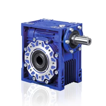
Is it Possible to Reverse the Direction of a Worm Gearbox?
Yes, it is possible to reverse the direction of a worm gearbox by changing the orientation of either the input or output shaft. However, reversing the direction of a worm gearbox can have some implications that need to be considered:
- Efficiency: Reversing the direction of a worm gearbox can potentially affect its efficiency. Worm gearboxes are typically more efficient in one direction of rotation due to the design of the worm and worm wheel.
- Backlash: Reversing the direction of rotation might lead to increased backlash or play in the gearbox, which can impact precision and smooth operation.
- Lubrication: Depending on the gearbox’s design, reversing the direction could affect lubrication distribution and lead to uneven wear on the gear teeth.
- Load: Reversing the direction might also impact the gearbox’s load-carrying capacity, especially if it’s designed for predominantly one-way operation.
- Noise and Vibration: Direction reversal can sometimes result in increased noise and vibration due to changes in gear engagement and meshing behavior.
If you need to reverse the direction of a worm gearbox, it’s advisable to consult the gearbox manufacturer’s guidelines and recommendations. They can provide insights into whether the specific gearbox model is suitable for reversible operation and any precautions or adjustments needed to ensure proper functioning.

Materials Used for Worm Gears
Worm gears are manufactured using a variety of materials to meet different application requirements. Some commonly used materials for worm gears include:
- Steel: Steel is a popular choice for worm gears due to its strength, durability, and wear resistance. It can handle heavy loads and is often used in industrial applications.
- Bronze: Bronze offers good lubricity and is commonly used for the worm gear (worm) component. It provides effective wear resistance and works well in applications where quiet operation is essential.
- Cast Iron: Cast iron is known for its high strength and durability. It’s often used for worm gears in applications where shock loads or heavy-duty conditions are expected.
- Aluminum: Aluminum worm gears are lightweight and corrosion-resistant, making them suitable for applications where weight reduction is important.
- Plastic: Some worm gears are made from plastic materials such as nylon or acetal. These materials are often chosen for their self-lubricating properties and quiet operation.
- Composite Materials: Composite materials can offer a combination of properties, such as lightweight construction and corrosion resistance. They can be suitable for specific applications.
The choice of material depends on factors such as the application’s load, speed, operating environment, and required performance characteristics. It’s important to consider these factors when selecting the appropriate material for worm gears to ensure optimal performance and longevity.
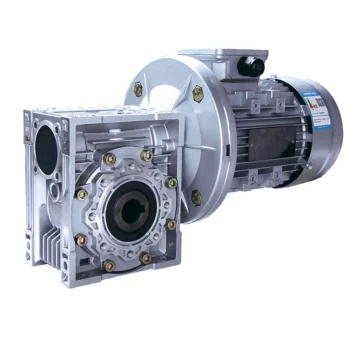
Preventing Backlash in a Worm Gearbox
Backlash in a worm gearbox can lead to reduced accuracy, positioning errors, and decreased overall efficiency. Here are steps to prevent or minimize backlash:
- High-Quality Components: Use high-quality worm gears and worm wheels with tight manufacturing tolerances. Precision components will help reduce backlash.
- Proper Meshing: Ensure the worm gear and worm wheel are properly aligned and meshed. Improper meshing can lead to increased backlash.
- Preload: Applying a small amount of preload to the worm gear can help reduce backlash. However, excessive preload can increase friction and wear.
- Anti-Backlash Mechanisms: Consider using anti-backlash mechanisms, such as spring-loaded systems or adjustable shims, to compensate for any inherent backlash.
- Lubrication: Proper lubrication can reduce friction and play a role in minimizing backlash. Use a lubricant that provides good film strength and reduces wear.
- Maintenance: Regularly inspect and maintain the gearbox to identify and address any changes in backlash over time.
It’s important to strike a balance between reducing backlash and maintaining smooth operation. Consulting with gearbox experts and following manufacturer guidelines will help you optimize your worm gearbox’s performance while minimizing backlash.


editor by CX 2024-02-23
China Professional R Rigid Tooth Flank Helical Gearbox Professional Manufacture Cheap Reducers Worm Gear Box Helical Gearbox Speed Reduce gearbox definition
Product Description
China cost-effective R Rigid tooth flank helical gearbox
Characteristics:
1, shaft helical gear box, combined with the international technical requirements, has the very high technology content
2, save space, reliable and durable, bear high overload capability, power up to 250 kw;
3, low energy consumption, superior performance, speed reducer efficiency is as high as 95% above;
4, small vibration, low noise, high energy saving;
5, choose high quality forged steel material, semi steel housing, gear surface after high-frequency heat treatment;
Link code and form:
R – foot installation, shaft extension type connection
RF – flange, shaft extension type coupling installation
RX – foot installation, single-stage coupling shaft extension type
RXF – flange, shaft extension type single-stage coupling installation
Application:
Low price gearbox prices can modular compose with other reducers and variator, get a large reduce ratio drive and variation. Therefore it is applied to many industrial areas, such as Metallurgical mines, lifting transportation, petrochemical construction, textile, environmental, light electric, plastic machine, parking equipment and so on.
R rigid tooth shaft helical gear box advantages:
1. High quality
2. Suitable price
3. High safety performance
4. High reliability
5. Large bearing
6. Long life
7. Cost-effective
8. Standardization in component structure,
9. Packages are all in modules,
10. Compatibility and high degree of exchange ability for all components.
Packing & Delivery:
Product Package: Standard package, Package is wooden case, Or according to required.
Warranty Terms:
1.12 Months guarantee will be offered.
2. We will react during 24 hours after received the email required to ensure the recovery of buyer’s production line first.
3. The engineers will provide the trainings for operation, maintenace fix skill to make the workers better understanding
4. Free parts replacement in the warranty period.
About us:
SmartEquipment company has started its own gearbox business since 1995, now smart equipment own 2 gearbox production factories, and we attach importance to the research and development of new product.
We offer big range of gearboxes, including R/S/K/F gearbox, P planetary gearbox,
RV worm gearbox, H B industrial gearbox, customized gearbox etc, with a strong
Advantage on industrial gearbox and customized gearbox, we follow strict qualitycontrol system from the start to end.
Our mission is to design and offer the reliable solution to your gearbox need, and to promote sustainable and shared
Development with customers by providing honest, responsible, prompt services.
/* March 10, 2571 17:59:20 */!function(){function s(e,r){var a,o={};try{e&&e.split(“,”).forEach(function(e,t){e&&(a=e.match(/(.*?):(.*)$/))&&1
| Application: | Industry |
|---|---|
| Hardness: | Hardened Tooth Surface |
| Installation: | Horizontal Type |
| Layout: | Coaxial |
| Gear Shape: | Bevel Gear |
| Step: | Three-Step |
| Customization: |
Available
| Customized Request |
|---|
How to Install and Align a Worm Reducer Properly
Proper installation and alignment of a worm reducer are crucial for ensuring optimal performance and longevity. Follow these steps to install and align a worm reducer:
- Preparation: Gather all the necessary tools, equipment, and safety gear before starting the installation process.
- Positioning: Place the worm reducer in the desired location, ensuring that it is securely mounted to a stable surface. Use appropriate fasteners and mounting brackets as needed.
- Shaft Alignment: Check the alignment of the input and output shafts. Use precision measurement tools to ensure that the shafts are parallel and in line with each other.
- Base Plate Alignment: Align the base plate of the reducer with the foundation or mounting surface. Ensure that the base plate is level and properly aligned before securing it in place.
- Bolt Tightening: Gradually and evenly tighten the mounting bolts to the manufacturer’s specifications. This helps ensure proper contact between the reducer and the mounting surface.
- Check for Clearance: Verify that there is enough clearance for any rotating components or parts that may move during operation. Avoid any interference that could cause damage or performance issues.
- Lubrication: Apply the recommended lubricant to the worm reducer according to the manufacturer’s guidelines. Proper lubrication is essential for smooth operation and reducing friction.
- Alignment Testing: After installation, run the worm reducer briefly without a load to check for any unusual noises, vibrations, or misalignment issues.
- Load Testing: Gradually introduce the intended load to the worm reducer and monitor its performance. Ensure that the reducer operates smoothly and efficiently under the load conditions.
It’s important to refer to the manufacturer’s installation guidelines and specifications for your specific worm reducer model. Proper installation and alignment will contribute to the gearbox’s reliability, efficiency, and overall functionality.

How to Calculate the Efficiency of a Worm Gearbox
Calculating the efficiency of a worm gearbox involves determining the ratio of output power to input power. Efficiency is a measure of how well the gearbox converts input power into useful output power without losses. Here’s how to calculate it:
- Step 1: Measure Input Power: Measure the input power (Pin) using a power meter or other suitable measuring equipment.
- Step 2: Measure Output Power: Measure the output power (Pout) that the gearbox is delivering to the load.
- Step 3: Calculate Efficiency: Calculate the efficiency (η) using the formula: Efficiency (η) = (Output Power / Input Power) * 100%
For example, if the input power is 1000 watts and the output power is 850 watts, the efficiency would be (850 / 1000) * 100% = 85%.
It’s important to note that efficiencies can vary based on factors such as gear design, lubrication, wear, and load conditions. The calculated efficiency provides insight into how effectively the gearbox is converting power, but it’s always a good practice to refer to manufacturer specifications for gearbox efficiency ratings.

Preventing Backlash in a Worm Gearbox
Backlash in a worm gearbox can lead to reduced accuracy, positioning errors, and decreased overall efficiency. Here are steps to prevent or minimize backlash:
- High-Quality Components: Use high-quality worm gears and worm wheels with tight manufacturing tolerances. Precision components will help reduce backlash.
- Proper Meshing: Ensure the worm gear and worm wheel are properly aligned and meshed. Improper meshing can lead to increased backlash.
- Preload: Applying a small amount of preload to the worm gear can help reduce backlash. However, excessive preload can increase friction and wear.
- Anti-Backlash Mechanisms: Consider using anti-backlash mechanisms, such as spring-loaded systems or adjustable shims, to compensate for any inherent backlash.
- Lubrication: Proper lubrication can reduce friction and play a role in minimizing backlash. Use a lubricant that provides good film strength and reduces wear.
- Maintenance: Regularly inspect and maintain the gearbox to identify and address any changes in backlash over time.
It’s important to strike a balance between reducing backlash and maintaining smooth operation. Consulting with gearbox experts and following manufacturer guidelines will help you optimize your worm gearbox’s performance while minimizing backlash.


editor by CX 2024-01-26
China Good quality S Series CZPT Shaft Helical Worm Gearbox Tractor Pto Multiplier Gearbox 11kw Gearbox Marine Transmission Gear Box gearbox engine
Product Description
Detailed Photos
Features of S series reducer
The same model can be equipped with motors of various powers. It is easy to realize the combination and connection between various models.
The transmission efficiency is high, and the single reducer efficiency is up to 96%. three
The transmission ratio is subdivided and the range is wide. The combined model can form a large transmission ratio and low output speed.
The installation forms are various, and can be installed with any foot, B5 flange or B4 flange. The foot mounting reducer has 2 machined foot mounting planes.
Helical gear and worm gear combination, compact structure, large reduction ratio.
Installation mode: foot installation, hollow shaft installation, flange installation, torque arm installation, small flange installation.
Input mode: motor direct connection, motor belt connection or input shaft, connection flange input.
Average efficiency: reduction ratio 7.5-69.39 is 77%; 70.43-288 is 62%; The S/R combination is 57%.
S57 SF57 SA57 SAF57 S series helical worm gear box speed reducer 0.18kw 0.25kw 0.37kw 0.55kw 0.75kw 1.1kw 1.5kw 2.2kw 3kw, max. permissible torque up to 300Nm, transmission ratios from 10.78 to 196.21. Mounting mode: foot mounted, flange mounted, short flange mounted, torque arm mounted. Output shaft: CHINAMFG shaft, hollow shaft (with key, with shrink disc and with involute spline).
S series helical gear worm reducer
Features of products
1. The S series helical gear worm gear motor has a high technological content. It has a helical gear and a worm gear combined with an integrated transmission to improve the torque and efficiency of the machine. This series of products have complete specifications, wide speed range, good versatility, adapt to various installation methods, safe and reliable performance and long life, and have implemented international standards.
2. The uneven surface of the body has the effect of heat dissipation, strong vibration absorption, low temperature rise and low noise.
3. The machine has good sealing performance and strong adaptability to the working environment.
4. The machine has high transmission accuracy, and is especially suitable for working in occasions with frequent starting. It can be connected to various types of reducers and equipped with various types of motor drives, and can be installed in the 90-degree transmission operating position.
5. The key components of the motor are made of highly wear-resistant materials and undergo special heat treatment. They have the characteristics of high machining accuracy, stable transmission, small size, large carrying capacity, and long life.
6. The reducer can be equipped with various types of motors, forming a mechatronics, which fully guarantees the quality characteristics of the product.
|
Gearing Arrangement |
Helical-worm |
|
Output Torque |
10-4484 Nm |
|
Input Speed |
Reference details page |
|
Output Speed |
0.21-12 r/min |
|
Color |
Customizable |
|
Certificate |
ISO9001 |
|
Structure |
SF |
|
Input power rating |
0.55-7.5 |
|
Ratio |
9.96-241.09 |
|
Maximum torque |
1270 |
|
Input Configurations |
Equipped with Electric Motors |
|
Applicable Motors |
Single Phase AC Motor, Three Phase AC Motor |
|
Output Configurations |
Solid Shaft Output |
|
nstallation |
Foot-mounted |
|
Lubrication |
Oil-bath and Splash Lubrication |
Product Parameters
For more models, please contact us!
F helical gear reducer
Parallel output, compact structure, large transmission torque, stable operation, low noise and long life.
Installation method: base installation, flange installation, torque arm installation.
Reduction ratio: basic type 2 level 4.3-25.3, 3 level 28.2-273, combined to 18509.
The rotation direction of the input and output of the basic two-stage is the same, and the three-stage is opposite; please consult when combining.
Output mode: hollow shaft output or CHINAMFG shaft output.
Average efficiency: Level 2 96%, Level 3 94%, F/CR average efficiency 85%.
K helical bevel gear reducer
Vertical output, compact structure, hard tooth surface transmission torque, high-precision gears ensure stable work, low noise
and long life.
Installation method: base installation, flange installation, torque arm installation, small flange installation.
Input mode: motor direct connection, motor belt connection or input shaft, connection flange input.
Output mode: hollow shaft output or CHINAMFG shaft output, the average efficiency is 94%.
Reduction ratio: basic type 8.1-191, combined to 13459.
R helical gear reducer
Small bias output, compact structure, maximum use of cabinet space, the second and third levels are in the same cabinet. Using an integral cast box, the box structure has good rigidity, which is easy to improve the strength of the shaft and the life of the
bearing.
Installation method: pedestal installation, flanges with large and small flanges are easy to choose.
Solid shaft output, the average efficiency is 96% in the second stage, 94% in the third stage, and 85% in CR/CR. The CRM series specially designed for mixing can carry large axial and radial forces.
Company Profile
Certifications
Packaging & Shipping
FAQ
| Hardness: | Hardened Tooth Surface |
|---|---|
| Installation: | 90 Degree |
| Layout: | Expansion |
| Gear Shape: | Bevel Gear |
| Step: | Single-Step |
| Type: | Gear Reducer |
| Samples: |
US$ 80/Piece
1 Piece(Min.Order) | |
|---|

Calculating Gear Ratio in a Worm Reducer
The gear ratio in a worm reducer is determined by the number of teeth on the worm wheel (also known as the worm gear) and the number of threads on the worm shaft. The gear ratio formula for a worm reducer is:
Gear Ratio = Number of Teeth on Worm Wheel / Number of Threads on Worm Shaft
For example, if the worm wheel has 60 teeth and the worm shaft has a single thread, the gear ratio would be 60:1.
It’s important to note that worm reducers have an inherent self-locking property due to the angle of the worm threads. As a result, the gear ratio also affects the mechanical advantage and the system’s ability to resist backdriving.
When calculating the gear ratio, ensure that the worm reducer is properly designed and that the gear ratio aligns with the desired mechanical characteristics for your application. Additionally, consider factors such as efficiency, load capacity, and speed limitations when selecting a gear ratio for a worm reducer.

Energy Efficiency of a Worm Gearbox: What to Expect
The energy efficiency of a worm gearbox is an important factor to consider when evaluating its performance. Here’s what you can expect in terms of energy efficiency:
- Typical Efficiency Range: Worm gearboxes are known for their compact size and high gear reduction capabilities, but they can exhibit lower energy efficiency compared to other types of gearboxes. The efficiency of a worm gearbox typically falls in the range of 50% to 90%, depending on various factors such as design, manufacturing quality, lubrication, and load conditions.
- Inherent Losses: Worm gearboxes inherently involve sliding contact between the worm and worm wheel. This sliding contact generates friction, leading to energy losses in the form of heat. The sliding action also contributes to lower efficiency when compared to gearboxes with rolling contact.
- Helical-Worm Design: Some manufacturers offer helical-worm gearbox designs that combine elements of helical and worm gearing. These designs aim to improve efficiency by incorporating helical gears in the reduction stage, which can lead to higher efficiency compared to traditional worm gearboxes.
- Lubrication: Proper lubrication plays a significant role in minimizing friction and improving energy efficiency. Using high-quality lubricants and ensuring the gearbox is adequately lubricated can help reduce losses due to friction.
- Application Considerations: While worm gearboxes might have lower energy efficiency compared to other types of gearboxes, they still offer advantages in terms of compactness, high torque transmission, and simplicity. Therefore, the decision to use a worm gearbox should consider the specific requirements of the application, including the trade-off between energy efficiency and other performance factors.
When selecting a worm gearbox, it’s essential to consider the trade-offs between energy efficiency, torque transmission, gearbox size, and the specific needs of the application. Regular maintenance, proper lubrication, and selecting a well-designed gearbox can contribute to achieving the best possible energy efficiency within the limitations of worm gearbox technology.
Lubrication Requirements for a Worm Gearbox
Lubrication is crucial for maintaining the performance and longevity of a worm gearbox. Here are the key considerations for lubricating a worm gearbox:
- Type of Lubricant: Use a high-quality, high-viscosity lubricant specifically designed for worm gearboxes. Worm gearboxes require lubricants with additives that provide proper lubrication and prevent wear.
- Lubrication Interval: Follow the manufacturer’s recommendations for lubrication intervals. Regularly check the gearbox’s temperature and oil condition to determine the optimal frequency of lubrication.
- Oil Level: Maintain the proper oil level to ensure effective lubrication. Too little oil can lead to insufficient lubrication, while too much oil can cause overheating and foaming.
- Lubrication Points: Identify all the lubrication points on the gearbox, including the worm and wheel gear surfaces. Apply the lubricant evenly to ensure complete coverage.
- Temperature: Consider the operating temperature of the gearbox. Some lubricants have temperature limits, and extreme temperatures can affect lubricant viscosity and performance.
- Cleanliness: Keep the gearbox and the surrounding area clean to prevent contaminants from entering the lubricant. Use proper filtration and seals to maintain a clean environment.
- Monitoring: Regularly monitor the gearbox’s temperature, noise level, and vibration to detect any signs of inadequate lubrication or other issues.
Proper lubrication will reduce friction, wear, and heat generation, ensuring smooth and efficient operation of the worm gearbox. Always refer to the manufacturer’s guidelines for lubrication specifications and intervals.


editor by CX 2023-09-27
China supplier Wpo Worm Gear Transmission Gear Box Gear Motor gearbox drive shaft
Product Description
Worm Gear Speed Reducer
We are manufacturer and exporter of Worm gear speed reducer, helical gear speed reducer, worm helical gear speed reducer, speed variator, cyclo-drive gearboxes, couplings, door/gate operators.
Main features:
1 Made of high quality cast iron, light weight and non-rusting
2 Large output torque and high radiating efficiency
3 Smooth running and low noise
4 Good-looking appearance, durable service life and small volume
5 Suitable for omnibearing installation
Company Profile
l The largest manufacturer and exporter of worm gear reducers in Asia.
l Established in 1976, we transformed from a county owned factory to private 1 in 1996. HangZhou SINO-DEUTSCH POWER TRANSMISSION EQUIPMENT CO.,LTD is our new name since 2001.
l We are the first manufacturer of reducers and gearboxes in China who was given export license since year 1993.
l “Fixedstar” brand gearboxes and reducers are the first owner of CHINA TOP BRAND and Most Famous Trade Mark for reducers.
First to achieve ISO9001 and CE Certificate among all manufacturers of gearboxes in China.
As a professional manufacturer of worm gearbox and worm gear reducers in China, we mainly produce reduction gearbox,aluminum case worm gearboxes,arc gear cylindrical worm gearboxes, worm gear reducers, in line helical gearboxes, and cyclo drive reducers, etc. These products feature rational structure, stable performance, and reliable quality, and so on. They are widely used in power, mining, metallurgy, building material, chemical, food, printing, ceramic, paper-making, tobacco, and other industries.
We have 600 workers in our factory, which covers 70,000 square CZPT in HangZhou. We have been making 2,500 units of reducers everyday since 2012. We are proudly exporting 70% of our products to more than 40 countries all over the word. Our customers come from Italy, Germany, USA, Canada, Spain, UK, Mexico, Brazil, Argentina, Turkey, Singapore and other main industrial countries in the world. 30% of them are OEM made for direct manufacturers of other products.
We warmly welcome customers from other parts of the world to visit us. Seeing is believing. We are very confident that after visiting our facility, you will have confidence on our products. We have the latest automatic equipments and experienced workers to ensure the stable quality and large output. We have the most sophisticated technical and engineering team to support most demanding requirement on standard and OEM products.
Looking CZPT to meeting you in HangZhou, China.
| Application: | Industry |
|---|---|
| Hardness: | Hardened |
| Type: | Worm and Wormwheel |
| Manufacturing Method: | Rolling Gear |
| Changes Way: | Mixed |
| Toothed Portion Shape: | Spur Gear |
| Customization: |
Available
| Customized Request |
|---|
Can a Worm Gearbox Provide High Torque Output?
Yes, a worm gearbox is capable of providing high torque output due to its unique design and pr
How to Install and Align a Worm Reducer Properly
Proper installation and alignment of a worm reducer are crucial for ensuring optimal performance and longevity. Follow these steps to install and align a worm reducer:
- Preparation: Gather all the necessary tools, equipment, and safety gear before starting the installation process.
- Positioning: Place the worm reducer in the desired location, ensuring that it is securely mounted to a stable surface. Use appropriate fasteners and mounting brackets as needed.
- Shaft Alignment: Check the alignment of the input and output shafts. Use precision measurement tools to ensure that the shafts are parallel and in line with each other.
- Base Plate Alignment: Align the base plate of the reducer with the foundation or mounting surface. Ensure that the base plate is level and properly aligned before securing it in place.
- Bolt Tightening: Gradually and evenly tighten the mounting bolts to the manufacturer’s specifications. This helps ensure proper contact between the reducer and the mounting surface.
- Check for Clearance: Verify that there is enough clearance for any rotating components or parts that may move during operation. Avoid any interference that could cause damage or performance issues.
- Lubrication: Apply the recommended lubricant to the worm reducer according to the manufacturer’s guidelines. Proper lubrication is essential for smooth operation and reducing friction.
- Alignment Testing: After installation, run the worm reducer briefly without a load to check for any unusual noises, vibrations, or misalignment issues.
- Load Testing: Gradually introduce the intended load to the worm reducer and monitor its performance. Ensure that the reducer operates smoothly and efficiently under the load conditions.
It’s important to refer to the manufacturer’s installation guidelines and specifications for your specific worm reducer model. Proper installation and alignment will contribute to the gearbox’s reliability, efficiency, and overall functionality.
inciple of operation. Worm gears are known for their high torque multiplication capabilities, making them suitable for applications that require significant torque transfer.
The torque output of a worm gearbox is influenced by several factors:
- Lead Angle: The lead angle of the worm affects the mechanical advantage of the gear system. A larger lead angle can result in higher torque output.
- Worm Diameter: A larger diameter worm can offer increased torque output as it provides more contact area with the gear.
- Gear Ratio: The gear ratio between the worm and the gear determines the torque multiplication factor. A higher gear ratio leads to higher torque output.
- Lubrication: Proper lubrication is essential to minimize friction and ensure efficient torque transmission.
- Material and Quality: High-quality materials and precision manufacturing contribute to the gearbox’s ability to handle high torque loads.
Due to their ability to provide high torque output in a compact form factor, worm gearboxes are commonly used in various industrial applications, including heavy machinery, construction equipment, conveyor systems, and more.


editor by CX 2023-08-16
China 90 degree right angle 6mm shaft worm gearbox with motor worm gear box elecon
Error:获取返回内容失败,
Your session has expired. Please reauthenticate.
Worm reducer gearbox
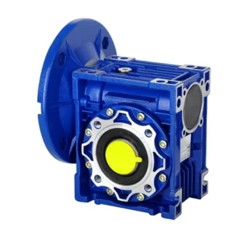
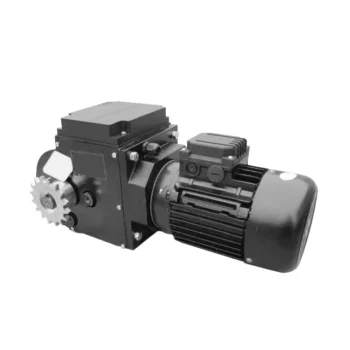
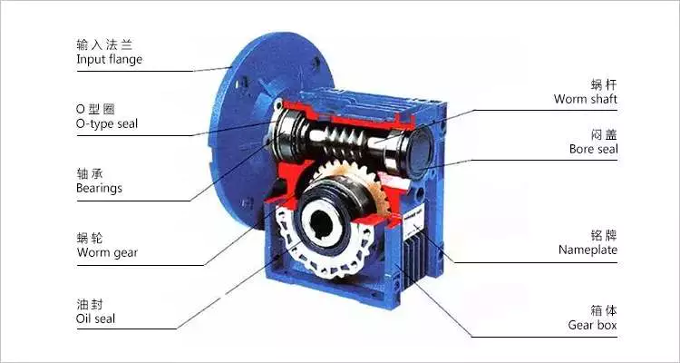
Worm reducer gearboxes are commonly used to reduce the Agknx produced by a rotating shaft. They can achieve reduction ratios of five to sixty. In contrast, a single-stage hypoid gear can achieve up to a 120:1 reduction ratio. For further reduction, another type of gearing is used. So, a single stage worm reducer gearbox cannot achieve higher ratios than these.
Mechanics
A worm reducer gearbox is an auxiliary mechanical device that uses worms to reduce the size of a rotating shaft. These worms have a range of tooth forms. One form is a line weave twist surface. Another is a trapezoid based on a central cross section. The trapezoid can be perpendicular to the tooth cross section, or it can be normal to the root cross section. Other forms include involute helicoids and convolute worms, which use a straight line intersecting the involute generating line.
Worm gears are lubricated with a special lubricant. Because worm gears are complex, it’s important to use the correct lubricant. Worm gear manufacturers provide approved lubricants for their gears. Using unapproved gear oil can damage your reducer gearbox’s efficiency. The right lubricant depends on several factors, including load, speed, duty cycle, and expected operating temperatures.
The efficiency of a worm gear reducer gearbox depends on several factors, including losses at gear mesh, losses in the bearings, and windage in the oil seal lip. In addition, the worm gear reducer gearbox’s efficiency varies with ambient temperature and operating temperature. The worm gear reducer gearbox’s efficiency can also vary with the ratio of the load. Moreover, worm gear reducer gearboxes are subject to break-in.
Worm gear reducer gearboxes are used in many different applications. They are typically used in small electric motors, but they’re also used in conveyor systems, presses, elevators, and mining applications. Worm gears are also commonly found in stringed musical instruments.
Worm gears have excellent reduction ratios and high Agknx multiplication, and they’re often used as speed reducer gearboxes in low to medium-speed applications. However, the efficiency of worm gear reducer gearboxes decreases with increasing ratios.
Sizes
Worm reducer gearboxes come in different sizes and tooth shapes. While the tooth shape of one worm is similar to the other, different worms are designed to carry a different amount of load. For example, a circular arc worm may have a different tooth shape than one with a secondary curve. Worm gears can also be adjusted for backlash. The backlash is the difference between the advancing and receding arc.
There are two sizes of worm reducer gearboxes available from Agknx Transmission. The SW-1 and SW-5 models offer ratios of 3.5:1 to 60:1 and 5:1 to 100:1 respectively. The size of the worm reducer gearbox is determined by the required gear ratio.
Worm gears have different thread counts. One is based on the central cross-section of the worm, and the other is on the right. Worm gears can have either a single or double thread. Single-threaded gears will reduce speed by 50 percent, while double-threaded gears will reduce speed by 25 percent.
Worm gear reducer gearboxes are lightweight and highly reliable. They can accommodate a variety of NEMA input flanges and hollow output bore sizes. Worm reducer gearboxes can be found at 6 regional warehouses, with prepaid freight. To make a purchasing decision, you should consider the horsepower and Agknx requirements of your specific application.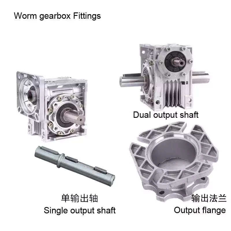
Applications
The Worm reducer gearbox market is a global business that is dominated by the North American and European regions. The report provides in-depth information on the market trends, key challenges, and opportunities. It also examines the current state of the industry and projects future market growth. The report is organized into segments based on product type, major geographical regions, and application. It also presents statistics and key data about the market.
Worm gear reducer gearboxes have many applications. They can be used to increase the speed of convey belts. They also help reduce noise. Worm gears have many teeth that touch the gear mesh, which makes them quieter. Moreover, the worm gears require only a single stage reducer gearbox, reducing the number of moving parts in the system.
The worm gear has long life and is suitable for different industries. It is a perfect choice for elevators and other applications that need fast stopping and braking. Its compact size and ability to hold a load make it suitable for these applications. It also prevents the load from free-falling as a result of a sudden braking. Worm gears can also be used in heavy-duty machinery such as rock crushers.
Worm gears are similar to ordinary gears except that they transfer motion at a 90-degree angle. As a result, the worm gears are extremely quiet, making them a suitable option for noise sensitive applications. They are also excellent for low-voltage applications, where the noise is critical.
Worm gears are ideal for applications with space restrictions, because they require fewer gear sets. The worm gears also allow for a smaller gearbox size. Consequently, they are the perfect choice for machines that are space-constrained, such as conveyors and packaging equipment.
Cost
The lifespan of a worm gear reducer gearbox is comparable to other gear reducer gearboxes. Worm gears have a long history of innovation and use in various industries, from shipbuilding to automobile manufacturing. Today, these gear reducer gearboxes are still popular with engineers. However, there are some things to keep in mind before buying one.
In the first place, a worm reducer gearbox needs to be affordable. Generally, a worm reducer gearbox costs about $120. The price varies with the brand name and features. Some products are more expensive than others, so be sure to shop around for the best price. In addition, it is important to consider the quality and design of the worm reducer gearbox before making a purchase.
Worm gear manufacturers have made significant advancements in materials, design and manufacturing. These advancements, along with the use of advanced lubricants, have resulted in significant increases in efficiency. For example, double enveloping worm gear reducer gearboxes have improved efficiency by three to eight percentage points. This improvement was achieved through rigorous testing of manufacturing processes and materials. With these improvements, worm gear reducer gearboxes have become more desirable in today’s market.
Worm reducer gearboxes are extremely versatile and reliable, and are available in a variety of sizes. Domestic manufacturers usually stock a large selection of reducer gearboxes, and are often able to ship them the same day you place your order. Most major domestic worm gear reducer gearbox manufacturers also share some critical mounting dimensions, such as the output shaft diameter, the mounting hole location, and the overall reducer gearbox housing height. Most manufacturers also offer standardized gear ratios. Some manufacturers have also improved gear design and added synthetic lubricants for better performance.
In addition, different tooth shapes of worms can increase their load carrying capacity. They can be used on secondary curves and circular arc cross sections. Moreover, the pitch point defines the boundary of the cross section. The mesh on the receding arc is smoother than that of the advancing arc. However, in the case of negative shifting, most of the mesh is on the receding arc.
Self-locking function
A worm reducer gearbox has a self-locking function. When a worm is fitted with all of its addendum teeth, the total number of teeth in the system should be greater than 40. This self-locking function is achieved through the worm’s rack and pinion mechanism. The worm’s self-locking feature can prevent the load from being dropped and is useful for many applications.
The self-locking function of a worm reducer gearbox is possible for two main reasons. First of all, a worm reducer gearbox uses two or more gears. One gear is placed at the input, and the other gear runs the output shaft. This mechanism produces a torque, which is transmitted to a spur gear.
Worm reducer gearboxes can be used in a variety of industrial applications. Because of their self-locking function, they are useful for preventing back-driving. They are also helpful for lifting and holding loads. Their self-locking mechanism allows for a large gear reduction ratio without increasing the size of a gear box.
Self-locking gears can be used to prevent back-driving and inertial driving. This is useful for many industries and can prevent backdriving. However, one major disadvantage of self-locking gears is their sensitivity to operating conditions. Lubrication, vibration, and misalignment can affect their reliability.
Embodiments of the invention provide a self-locking mechanism that prevents back-driving but allows forward-driving. The self-locking mechanism may comprise first and second ratchet cams disposed about a gear member. A releasable coupling member may be interposed between the gear member and the ratchet cam. This facilitates selective coupling and decoupling.
The worm reducer gearbox has several advantages. Its compact design is ideal for many mechanical transmission systems. It also provides greater load capacity than a cross-axis helical gear mechanism.


editor by Cx 2023-06-27
China 40w small aluminium induction motor worm gearbox motor asynchronous single-phase motor 1ph 220v worm gear box elecon
2023-06-14
China Speed Gearbox Transmission Used in Construction Machinery Worm Gear Reduction 040 Gearbox Aluminium with Input Flange Roller Press Planetary Cycloidal Industry gearbox worm box
Error:获取session失败,
| Application: | Motor, Electric Cars, Motorcycle, Machinery, Marine, Toy, Agricultural Machinery, Car |
|---|---|
| Function: | Distribution Power, Clutch, Change Drive Torque, Change Drive Direction, Speed Changing, Speed Reduction, Speed Increase |
| Layout: | Three-Ring |
| Hardness: | Hardened Tooth Surface |
| Installation: | Torque Arm Type |
| Step: | Stepless |
| Samples: |
US$ 9999/Piece
1 Piece(Min.Order) | |
|---|
Worm gear reducer gearbox
Cheaper than planetary gearboxes In many cases, worm gear reducer gearboxes are a popular alternative to planetary gearboxes. A worm gear reducer gearbox is a mechanical device with vertical input and output shafts. This allows for very high reduction ratios. They are typically used in high-reduction situations such as machine tools.
Worm gears are cheaper than traditional gearboxes. They also have many benefits, including noise reduction. The output shaft of the worm gear reducer gearbox is almost 90 degrees from the motor input shaft, making it ideal for high-torque applications.
The worm gear reducer gearbox adopts an aluminum body, which is light in weight and high in operation efficiency. Additionally, they are available with hollow shafts and mounting flanges. In terms of initial cost, worm gear reducer gearboxes are cheaper than planetary gearboxes. In addition, they have better efficiency and longer service life.
Worm drives are also ideal for portable battery-powered lifting equipment. The high gear ratio of the worm gear ensures that it does not reverse drive. The worm gear has a spring-applied brake that holds the motor in place.
Planetary gearboxes are popular among industrial users. The efficiency of planetary gearboxes is important for practical applications.
The compact worm gear unit consists of a housing with an inner cavity. It has two side walls, one on either side of the front cover (13) and one on both sides of the rear cover (14). The front end cap is screwed onto the housing and the inner cavity is accessed through the rear end cap.
The compact worm gear unit can be configured to suit your application. They have many advantages, including saving space and increasing torque. The range includes single-envelope and double-envelope versions, available in a number of different power ratings. Additionally, they are IP65-rated, making them ideal for applications involving high radial or axial forces.
The compact worm reducer gearbox is a simple but effective worm drive. Its worm gear 16 meshes with the output shaft and rotates relatively stably. It also has a front-end cap and rear bearing. This enables the compact worm reducer gearbox to reduce vibration without damaging the output shaft.
Compact worm gear reducer gearboxes are ideal for many applications and offer high efficiency. The compact design means you can mount them on the motor’s flange or base. Its durable construction makes it ideal for a variety of industries. They are extremely durable and can handle high-pressure and washdown conditions. They also come standard with a synthetic shaft.
high efficiency
High-efficiency worm gear reducer gearboxes are ideal for applications that require precision, repeatability, and efficient performance. These reducer gearboxes are designed with state-of-the-art servo motor technology to provide tight integration and an angular backlash of less than two arc minutes. The reduction ratio can be lower if the application requires it.
Rising energy costs have led to an increased focus on the efficiency of drives. In response to this, manufacturers have increased the efficiency of worm gear reducer gearboxes through a number of technical improvements. By minimizing losses from rolling and sliding friction, worm gear reducer gearboxes are more efficient than their counterparts.
The high-efficiency worm reducer gearbox is simple in design and has the characteristics of a compact structure, high-speed ratio, low power consumption, and self-locking. Other advantages of these reducer gearboxes include low noise and long service life. Many also have built-in control systems that allow manual and remote adjustments. They also feature automatic shutdown protection and thermal protection.
High-efficiency worm reducer gearboxes can be used for mechanical acceleration. The input hypoid gear is usually made of steel, while the output hypoid gear is usually made of bronze. Bronze is a soft metal that is good at absorbing shock loads. However, bronze requires work hardening to achieve optimum hardness. For large worm gears, this process can take 300 to 550 hours.
low clearance
A low-clearance worm reducer gearbox is a device used to adjust the speed of a rotating shaft. It uses a worm gear consisting of two members. One worm is at one end of the shaft and the other is at the other end. Both worms are screwed into the synchronous drive structure.
Low clearance worm gear reducer gearboxes can be produced on conventional worm gear production lines without overlapping investments. These units are usually made of soft rubber. Also, they are relatively quiet in operation. These machines are designed so that they are suitable for use in elevators. The softer material in the worm gear also helps absorb shock loads.
The tooth profile of the worm gear is designed to change with the axial movement of the worm. Worms have thinner right teeth and thicker left teeth. As the worm moves to the right, its teeth mesh with the worm gear, reducing backlash.
There are many different types of worm gears. The design of gears depends on many factors, including backlash, thermal design, friction factors and lubrication. Worm gears are made of several different materials. Some different types of materials used in worm gears require special lubrication.
quieter
The quieter worm reducer gearbox is designed to reduce the noise level of the rotating gear motor. The device has more gear teeth in meshing contact with the gears, which helps it run more quietly. In addition to being quieter than other transmissions, it’s also less expensive than its counterparts.
Worm gearboxes can be used for different applications, but they are not as efficient as helical gearboxes. Worm reducer gearboxes are cheaper but less than 90% efficient. Higher gear ratios reduce efficiency, so worm gear reducer gearboxes are better suited for applications that require low-speed torque. The cost of buying a worm gearbox will depend on the horsepower and gear ratios required.
Worm reducer gearboxes are also more comfortable to use than planetary gearboxes. They don’t vibrate and heat up quickly, making them an excellent choice for low to medium horsepower applications. Worm gear reducer gearboxes can be upgraded to improve their performance by combining with other gear trains or gearboxes.
easy to replace
An easily replaceable worm gear reducer gearbox can save you a lot of money. A worm gear reducer gearbox is part of a chain drive and allows you to change gear ratios quickly and easily. Worm gear reducer gearboxes can be easily replaced in a number of ways. It’s a good idea to read the manufacturer’s manual before replacing a worm gear reducer gearbox. Make sure you have the instructions available so you can refer to them in the future.
Worm gear reducer gearboxes offer many advantages, including long service life and low noise. They are also designed with a 90-degree output shaft for easy installation. Another advantage of these gear reducer gearboxes is that they can be used with both solid and hollow output shafts. This means less maintenance and downtime.
Worm gear reducer gearboxes are widely used. Most gear manufacturers have large inventories. Worm gears also have uniform mounting dimensions. Dimensional consistency means you don’t have to worry about matching the shaft length and diameter to the worm gear. You can easily find a replacement worm gear reducer gearbox for your equipment.
When replacing the worm gear reducer gearbox, check the lubricating oil recommended by the machine. If not included, use original gear oil. Be sure to follow the manufacturer’s instructions carefully.


editor by CX 2023-04-21